
Acquisition Shackle Seal PRR Patent USA102481815
Acquired: 11/19/2021 from Facebook marketplace and donated by Greg Mester. Story from seller is that the 28 pieces were a part of an estate sale.
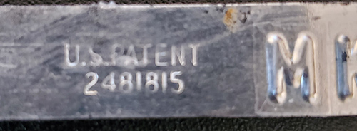
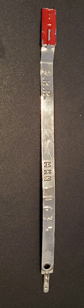
The marking on the tie include:
- PRR
- MKN with a numbering sequence We have 28 units in all.
- U.S. Patent 2481814, which is really USA102481814
SHACKLE SEAL
Information obtained from the US Patent office search site
Patented Sept. 13, 1949 Patent 2,481,815 United States Patent Office
Winfred M. Brooks, West Orange, N. J., assignor to E. J. Brooks Company, Newark, N. J, a corporation of New Jersey
Application March 10, 1948, Serial No 13,990
3 Claims. (Cl. 292—317)
This invention relates to self-locking shackle seals composed of a band of sheet-material having a head at one end for the reception of the other and free end of a reverse-section when said band is doubled back upon itself and the reverse-section is inserted in the head.
All seals of this type can be opened, and the object of this invention is to so construct the seal that it will take a relatively long time to open it once it has been closed, and that evidence of tampering will clearly appear if it is attempted to open the seal, so that an unscrupulous person will likely be discouraged from completely opening the seal when he realizes that evidence of tampering cannot be avoided.
In the accompanying drawings, the invention is disclosed in a concrete and preferred form in which :
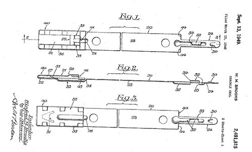
Figure 1 is a plan view of the seal in its open position
Figure 2 is a longitudinal sectional view substantially on the plane of line 2—2 of Figure 1;
Figure 3 is a view similar to Figure 1 but showing the reverse face of the seal;
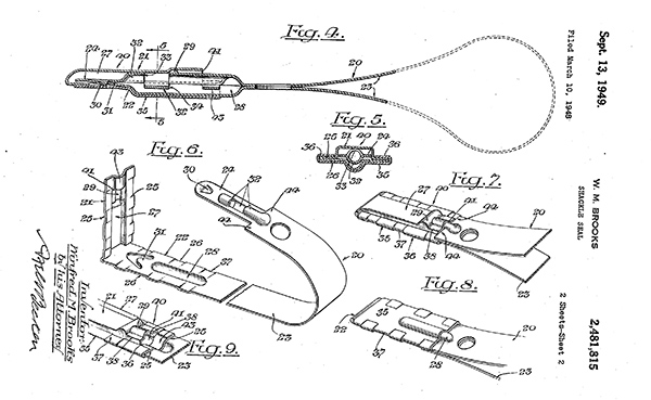
Figure 4 is a view similar to Figure 2 but on a larger scale and with the seal in its closed position;
Figure 5 is a transverse sectional view substantially on the plane of line 5—5 of Figure 4; Figure 6 is a perspective view of the seal with the channel member removed, with the end-section of the shackle bent away from the headsection so as to expose the interior of the head of the seal, and with the shackle bent so as to expose the underside of the reverse-section;
Figure „7 is a perspective view of one face of the head of the seal with the parts in closed position;
Figure 8 is a view similar to Figure 7 but showing the reverse face of the head of the seal; and Figure 9 is a fragmentary perspective view of the head of the seal, similar to Figure 7, but with the reverse-section removed.
20 indicates a band of sheet-material comprising, in the order named, an end-section 21, a head-section 22, a main-section 23 and a reverse-section 24, which latter is narrower than the other sections. End-section 2 f lies folded back longitudinally over head-section 22 and has longitudinally extending marginal depressions 25 to overlie, engage and be secured to longitudinal marginal face portions 26 of head-section 22, to form a head 40, narrower than said band, provided with an opening 4t for the reception of reverse-section 24. Said end-section 21 and said
head-section 22 have complementary and longitudinal grooves 27 and 28 that extend centrally thereof for the reception of the longitudinal beads, presently to be described, in said reverse5 section 24. 29- indicates one or more transverse weakened zones in end-section 21, one of which preferably lies at the terminus of longitudinal groove 27. Said reverse-section 24 and headsection 22 have complementary interlocking
10 means which, in the present instance, consist of two spurs or prongs 30 and 31 that interlock when reverse-section 24 is inserted a sufficient distance into head 40 and it is attempted to pull it out again. 32 indicates three longitudinal 15 beads pressed from opposite faces of reverse-section 24, which beads lie in the complementary grooves in end-section 21 and head-section 22, when said reverse-section 24 is in position in head 40. These beads constitute abutments that 20 block access to the inter-locking means and it will be seen that abutment 33 will be encountered by a tool inserted between reverse-section 24 and end-section 21, and that the other abutment 34 will be encountered by a tool inserted 25 between reverse-section 24 and head-section 22. It will further be seen that beads 32 also constitute one or more transverse weakened zones in reverse-section 24. 35 indicates a channel member of sheet-material that embraces head-section 22 and which is provided with marginal flanges 36 that overlie marginal depressions 25 of end-section 21, and said head-section, endsection and channel member 35 are secured together by transverse crimps 37.
If it is now attempted to separate end-section 21 from head-section 22, by means of a tool, one or the other of abutments 33 or 34 will constitute a fulcrum for the tool and will cause the material to tear longitudinally along lines 38 and 4-0 will direct bending of end-section 21 along one or more weakened zones 29 which will either cause a rupture of said weakened zone or will deform the material to such an extent that clear evidence of tampering will be evident. Should 45 it be attempted to separate prongs 30 and 31 by pulling them apart without attempting to pry open the end-section, then the metal of said reverse-section will become ruptured, by reason of the weakened zone formed by beads 32, and will 50 thus frustrate the attempt to open the seal.
Provision is however made whereby it will be exceedingly difficult to insert a tool in the manner indicated or to pry up marginal flanges 36 of channel member 35. For it will be noted that marginal 55 depressions 25 of end-section 21 extend longitudinally beyond opening 41 of head 40, and are connected by a transversely extending lip 43 which forms a part of end-section 21 and is located in front of said opening 41. Marginal flanges 36 of channel member 35 likewise extend beyond opening 41. It will therefore be seen, when reverse section 24 is inserted over lip 43 and through opening 41 and in between end-section 21 and head—section 22, that that part 44 of main-section. 23 that is adjacent reverse-section 24 overlies lip 43 and the ends of marginal flanges 36 of the channel member.
I claim:
At the museum we are always picking up small acquisitions related to Railroads in and around the Philadelphia area.